Basic indication table
| Status | Blue LED |
Red LED |
Green LED |
|---|---|---|---|
| Back-up mode | |||
| Normal mode | |||
| Regulator error | |||
| Battery recovery | |||
| Battery protection error |
LED ON LED OFF

12V battery CCTV Electronics
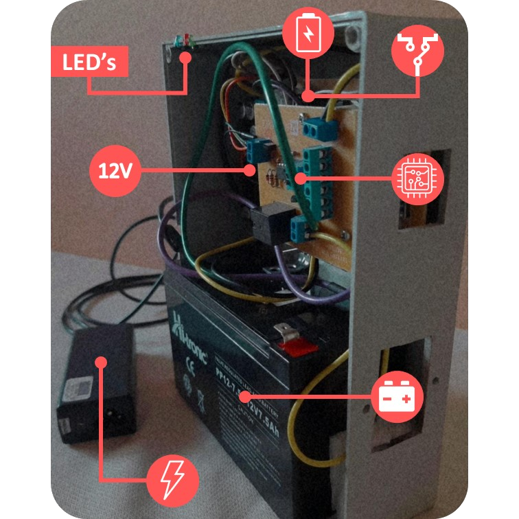
Electronic device that provides battery back-up, when the electrical power fails, to a wifi modem and CCTV system. The uninterrupted power supply (UPS) system provides enough power for several hours (depending of battery capacity) with a stable voltage of 12V.
The UPS implements a 12V rechargeable sealed battery and a set of electronic circuits responsible for maintaining a stable output voltage, charging the battery and protecting it against over-discharge or over-current.
| Status | Blue LED |
Red LED |
Green LED |
|---|---|---|---|
| Back-up mode | |||
| Normal mode | |||
| Regulator error | |||
| Battery recovery | |||
| Battery protection error |

The operation of the system is divided into two segments according to electric power.
Normal electric power: in this stage the operation is as shown in Figure A. The UPS will charge the battery automatically; the power supply is connected to the city power and its output goes to the commutator. Because there's electrical energy, the commutator contacts are connected to the power supply, then its ouput goes to a 12V regulator and finally give power to the ouput devices.
Back-up mode: in this stage the operation is as shown in Figure B. Because there's not electrical energy, the power supply and battery charger doesn't work; the commutator contacts are connected to the battery protection circuit and then its ouput goes to the 12V regulator wich supplies the ouput devices.
The characterization of the UPS system and its behavior over time are presented below, through a monitoring circuit. The circuit carried out the respective measurements, saved the information in a microSD memory in a stipulated time interval and then it was processed with a python and Excel script (see more information in the following repository). For the following battery charge and discharge curves, place the cursor on the graph to interact with it.
Battery duration: total time that the UPS system can keep the devices energized, when the electric power fails, with the battery fully charged.
Battery recovery: time the battery is available (when charging) for use again after being fully discharged.
Recharge time: time the battery is fully charged after being fully discharged.
Consumption current: average current to which the battery discharge curve was subjected.
Temperature: average ambient temperature at which the monitoring of the charging and discharging battery curves were carried out.
Sampling period: time interval between two successive samples.